Where Is the Fuse for a Horn on a 2005 Ford F350
See other Ford F-250 / F-350 / F-450 / F-550:


Fuse Layout Ford F250 / F350 / F450 / F550 2005-2007
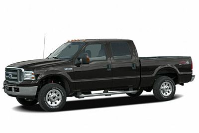
Pocket lighter (power outlet) fuses in the Ford F-250 / F-350 / F-450 / F-550 are the fuses №4 (Power point (Instrument panel)) and №12 (Cigar lighter) in the Instrument panel fuse box seat.
Rider compartment
The fuse panel is located below and to the left hand of the steering wheel past the brake pedal behind the panel. 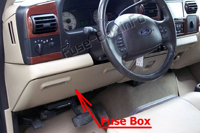
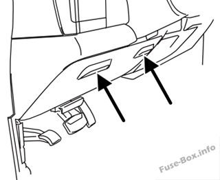

Engine compartment
The power distribution box is located in the railway locomotive compartment. 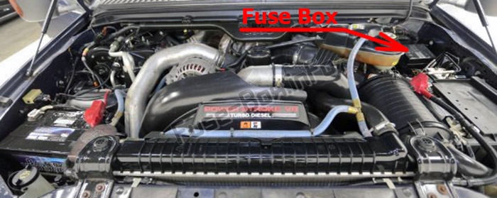
2005
Rider compartment
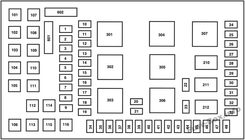
Assignment of the fuses in the Passenger compartment (2005)
| № | Amp Rating | Verbal description |
|---|---|---|
| 1 | 15 A* | Changeful pedals |
| 2 | 10 A* | Bunch up |
| 3 | 10 A* | Upfitter #3 |
| 4 | 20 A* | Office point (Control panel) |
| 5 | 10 A* | Upfitter #4 |
| 6 | — | Non used |
| 7 | 30A* | High beam headlamps, Flash-to-pass |
| 8 | 20 A* | Back-up lamps |
| 9 | — | Non used |
| 10 | — | Non used |
| 11 | 20 A* | Radio (Main) |
| 12 | 20 A* | Cigar igniter, OBD II |
| 13 | 5A* | Power mirrors |
| 14 | — | Not used |
| 15 | — | Non utilized |
| 16 | — | Not used |
| 17 | 15 A* | Outdoor lamps |
| 18 | 20 A* | Flasher, Pasture brake On-Turned (BOO) lamps |
| 19 | 10 A* | Body Security measur Module (BSM) (Security measur) |
| 20 | 15 A* | Dawdler tow Electric Brake Controller (EBC) |
| 21 | 20 A* | Heated up seats |
| 22 | 20 A* | Engine control |
| 23 | 20 A* | Engine control (gasoline locomotive engine entirely)/Mood control (Diesel motor only) |
| 24 | 15 A* | Tow hale, Cetacean mammal electrical relay, Electronic Automatic Temperature Moderate (EATC) |
| 25 | — | Not used |
| 26 | 10 A* | Air bags |
| 27 | 15 A* | Lighting switch RUN feed |
| 28 | 10 A* | Trailer tow EBC logic |
| 29 | 10 A* | Customer access |
| 30 | 15 A* | High shaft headlamps |
| 31 | 15 A* | 4x4 |
| 32 | 5A* | Radio receiver (start) |
| 33 | 15 A* | Cluster, 4x4, Wipers |
| 34 | 10 A* | Snort switch (Low current) |
| 35 | 10 A* | Instrument cluster |
| 36 | — | Not used |
| 37 | 15 A* | Cornet |
| 38 | 20 A* | House trailer tow common lamps |
| 39 | 15 A* | Het mirrors |
| 40 | 20 A* | Fuel pump |
| 41 | 10 A* | Instrument cluster |
| 42 | 15 A* | Delayed accessoiy |
| 43 | 10 A* | Fog lamps |
| 44 | — | Non used |
| 45 | 10 A* | Ignition switch Track down/START feed in |
| 46 | 10 A* | Left low beam headlamp |
| 47 | 10 A* | Right-give bass irradiatio headlamp |
| 48 | — | Not in use |
| 101 | 30A** | Trailer tow EBC |
| 102 | 30A** | BSM (Door locks) |
| 103 | 30A** | Ignition change |
| 104 | — | Not put-upon |
| 105 | — | Non used |
| 106 | — | Not used |
| 107 | 20A** | Trailer tow battery charge |
| 108 | 30A** | UpFitter #1 |
| 109 | 30A** | UpFitter #2 |
| 110 | 30A** | Ignition switch |
| 111 | — | Not used |
| 112 | 30A** | Power behind (Driver) |
| 113 | 30A** | Starter |
| 114 | 30A** | Power seat (Passenger) |
| 115 | 20A** | UpFitter control |
| 116 | 30A** | Ignition switch |
| 210 | — | Not used |
| 211 | 1/2 ISO relay | Back-high lamps |
| 212 | — | Not used |
| 301 | Full ISO relay | Trailer tow battery charge |
| 302 | High ISO electrical relay | Powertrain Manipulate Module (PCM) |
| 303 | — | Not used |
| 304 | — | Not used |
| 305 | Full ISO relay | UpFitter ascertain |
| 306 | Entire ISO electrical relay | Delayed accessoiy |
| 307 | Full ISO electrical relay | Appetiser |
| 601 | 30A breaker | Suspended accessoiy, World power windows, Moonroof |
| 602 | — | Non used |
| * Mini fuse ** Cartridge fuse |
Engine compartment
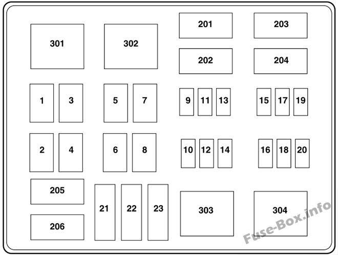
Naming of the fuses in the Power distribution box (2005)
| № | Amp Valuation | Description |
|---|---|---|
| 1 | 30A* | Wipers |
| 2 | 40A* | Blower |
| 3 | 30A* | Lepton Shift on the Fly (ESOF) |
| 4 | — | Not used |
| 5 | 50A* | Injector Number one wood Module (IDM) (Diesel engine only) |
| 6 | — | Not in use |
| 7 | 30A* | Naiant Fire Conditioner Module (HFCM) (Rudolf Christian Karl Diesel railway locomotive only) |
| 8 | — | Non used |
| 9 | 20A** | Trailer tow turn signals |
| 10 | 10A** | Powertrain Ascendancy Module (PCM) keep alive power, Canister vent-hole solenoid (gasoline locomotive only) |
| 11 | 10A** | Anti-lock Pasture brake Arrangement (ABS) |
| 12 | 2A** | Brake pressure switch |
| 13 | 15 A** | Daytime Running Lamps (DRL) |
| 14 | — | Non used |
| 15 | 15A** | IDM logic (Diesel only) |
| 16 | — | Not secondhand |
| 17 | 10A** | A/C clutch |
| 18 | 10A** | IDM relay (Diesel motor only) |
| 19 | — | Non used |
| 20 | 10A** | Trailer tow back-in the lead lamps |
| 21 | — | Not used |
| 22 | 60A*** | ABS (Coils) |
| 23 | 60a*** | ABS (Ticker) |
| 201 | 1/2 ISO relay | Trailer tow right blinker/stop lamp |
| 202 | 1/2 ISO relay | Trailer towage left good turn bespeak/stop lamp |
| 203 | 1/2 ISO relay | A/C clutch |
| 204 | — | Not in use |
| 205 | 1/2 ISO relay | DRL #1 |
| 206 | 1/2 ISO electrical relay | DRL #2 |
| 301 | Full ISO relay | DRL #3 |
| 302 | Full ISO relay | HFCM |
| 303 | Full ISO electrical relay | Cetacean |
| 304 | Alto-current relay | IDM (Diesel engine only) |
| * Cartdrige Fuse ** Mini Fuses *** Maxi fuse |
2006
Rider compartment

Assignment of the fuses in the Passenger compartment (2006)
| № | Ampere Rating | Description |
|---|---|---|
| 1 | 15 A* | Adaptable pedals |
| 2 | 10 A* | Bunch |
| 3 | 10 A* | Upfitter #3 |
| 4 | 20 A* | Ability point (Pane) |
| 5 | 10 A* | Upfitter #4 |
| 6 | — | Non used |
| 7 | 30A* | High beam headlamps, Flash-to-pass |
| 8 | 20 A* | Back-up lamps |
| 9 | — | Non used |
| 10 | — | Not used |
| 11 | 20 A* | Radio (Main) |
| 12 | 20 A* | Cigarette lighter, OBD II |
| 13 | 5A* | Power mirrors |
| 14 | — | Not used |
| 15 | — | Non used |
| 16 | — | Not used |
| 17 | 15 A* | Outside lamps |
| 18 | 20 A* | Flasher, Brake On-Off (Raspberry) lamps |
| 19 | 10 A* | Body Security Module (BSM) (Security) |
| 20 | 15 A* | Trailer tow Electric Pteridium aquilinu Controller (EBC) |
| 21 | 20 A* | Heated seating room |
| 22 | 20 A* | Engine control |
| 23 | 20 A* | Railway locomotive ascertain (gasoline railway locomotive only)/Climate control (Diesel only) |
| 24 | 15 A* | Towage haul, Blower relay, Electronic Automatic Temperature Control (EATC) |
| 25 | — | Not utilized |
| 26 | 10 A* | Airbags |
| 27 | 15 A* | Ignition shift RUN flow |
| 28 | 10 A* | Preview towage EBC logic |
| 29 | 10 A* | Customer access |
| 30 | 15 A* | High beam headlamps |
| 31 | 15 A* | Starter relay |
| 32 | 5A* | Radio (start) |
| 33 | 15 A* | Cluster, 4x4, Wipers |
| 34 | 10 A* | BOO exchange (Scurvy current) |
| 35 | 10 A* | Musical instrument cluster |
| 36 | — | Non utilised |
| 37 | 15 A* | Horn |
| 38 | 20 A* | Trailer tow park lamps |
| 39 | 15 A* | Heated mirrors |
| 40 | 20 A* | Fuel pump |
| 41 | 10 A* | Instrument cluster |
| 42 | 15 A* | Delayed accessoiy |
| 43 | 10 A* | Fog lamps |
| 44 | — | Not used |
| 45 | 10 A* | Ignition switch RUN/START feed |
| 46 | 10 A* | Left-hand low beam headlamp |
| 47 | 10 A* | Right-hand rock-bottom beam headlamp |
| 48 | — | Not used |
| 101 | 30A** | Trailer tow EBC |
| 102 | 30A** | BSM (Doorway locks) |
| 103 | 30A** | Kindling switch |
| 104 | — | Not used |
| 105 | — | Not used |
| 106 | — | Not used |
| 107 | 20A** | Dawdler tow battery charge |
| 108 | 30A** | UpFitter #1 |
| 109 | 30A** | UpFitter #2 |
| 110 | 30A** | Ignition switch |
| 111 | — | Non used |
| 112 | 30A** | Power seat (Driver) |
| 113 | 30A** | Starter |
| 114 | 30A** | Power seat (Rider) |
| 115 | 20A** | UpFitter control |
| 116 | 30A** | Ignition switch |
| 210 | — | Not old |
| 211 | 1/2 ISO relay | Back-risen lamps |
| 212 | — | Not used |
| 301 | Full ISO relay | Trailer towage battery charge |
| 302 | Full ISO relay | Powertrain Control Module (PCM) |
| 303 | — | Not used |
| 304 | — | Not used |
| 305 | Full ISO electrical relay | UpFitter control |
| 306 | Full ISO relay | Held up accessoiy |
| 307 | Full ISO electrical relay | Dispatcher |
| 601 | 30A circuit breaker | Delayed accessoiy, Top executive Windows, Moonroof |
| 602 | — | Non put-upon |
| * Miniskirt fuse ** Cartridge fuse |
Engine compartment

Designation of the fuses in the Power distribution boxful (2006)
| № | Amp Rating | Verbal description |
|---|---|---|
| 1 | 30A* | Wipers |
| 2 | 40 A* | Blower |
| 3 | 30A* | Electronic Shift on the Fly (ESOF) |
| 4 | — | Non used |
| 5 | 50A* | Injector Driver Mental faculty (IDM) (Diesel railway locomotive entirely) |
| 6 | — | Non used |
| 7 | 30A* | Horizontal Fuel Conditioner Module (HFCM) (Diesel engine engine only when) |
| 8 | — | Bypass |
| 9 | 20A** | Trailer tow turn signals |
| 10 | 10A** | Powertrain Control Module (PCM) keep alive power, Canister vent solenoid (gasoline engine only) |
| 11 | 10A** | Anti-lock Brake System (ABS) |
| 12 | 2A** | Pasture brake pressure flip |
| 13 | 15A** | Daytime Running Lamps (DRL) |
| 14 | — | Not used |
| 15 | 15A** | IDM logic (Diesel only) |
| 16 | — | Not used |
| 17 | 10A** | A/C clutch |
| 18 | 10A** | IDM relay (Rudolf Diesel locomotive only) |
| 19 | — | Not secondhand |
| 20 | 10A** | House trailer tow indorse-up lamps |
| 21 | — | Not used |
| 22 | 60A*** | ABS (Coils) |
| 23 | 60A *** | ABS (Pump) |
| 201 | 1/2 ISO relay | Dawdler tow right trafficator/lay of lamp |
| 202 | 1/2 ISO electrical relay | Dawdler tow left turn indicator/stop lamp |
| 203 | 1/2 ISO relay | A/C clutch |
| 204 | — | Not old |
| 205 | 1/2 ISO relay | DRL #1 |
| 206 | 1/2 ISO relay | DRL #2 |
| 301 | Full ISO electrical relay | DRL #3 |
| 302 | Overfull ISO relay | HFCM |
| 303 | Full ISO relay | Cetacean |
| 304 | High-current relay | IDM (Diesel engine only) |
| * Cartridge Fuse ** Mini Fuses *** Maxi fuse |
2007
Passenger compartment

Duty assignment of the fuses in the Rider compartment (2007)
| № | Amp Rating | Description |
|---|---|---|
| 1 | 15 A* | Adjustable pedals |
| 2 | 10 A* | Cluster |
| 3 | 10 A* | Upfitter #3 |
| 4 | 20 A* | Power point (Instrument panel) |
| 5 | 10 A* | Upfitter #4 |
| 6 | — | Non secondhand |
| 7 | 30A* | High beam headlamps, Flash-to-pass |
| 8 | 20 A* | Back up-heavenward lamps |
| 9 | — | Not used |
| 10 | — | Not used |
| 11 | 20 A* | Radio (Main) |
| 12 | 20 A* | Pocket lighter, OBD II |
| 13 | 5A* | Power mirrors |
| 14 | — | Not used |
| 15 | — | Not used |
| 16 | — | Not used |
| 17 | 15 A* | Exterior lamps |
| 18 | 20 A* | Flasher, Brake On-Off (Raspberry) lamps |
| 19 | 10 A* | Consistency Security system Module (BSM) (Security) |
| 20 | 15 A* | Trailer tow Tense Brake Controller (EBC) |
| 21 | 20 A* | Heated up seats |
| 22 | 20 A* | Engine control |
| 23 | 20 A* | Engine controller (gasoline engine only)/Climate control (Diesel only) |
| 24 | 15 A* | Tow drag, Blower relay, Electronic Automatic Temperature Control (EATC) |
| 25 | — | Not used |
| 26 | 10 A* | Airbags |
| 27 | 15 A* | Ignition switch Run along fertilize |
| 28 | 10 A* | Trailer tow EBC logic |
| 29 | 10A* | Customer access |
| 30 | 15 A* | Falsetto beam headlamps |
| 31 | 15 A* | Starter electrical relay |
| 32 | 5A* | Radio (start) |
| 33 | 15 A* | Cluster, 4x4, Wipers |
| 34 | 10 A* | BOO flip (Low current) |
| 35 | 10 A* | Instrument cluster |
| 36 | — | Not used |
| 37 | 15 A* | Horn |
| 38 | 20 A* | Trailer towage park lamps |
| 39 | 15 A* | Heated mirrors |
| 40 | 20 A* | Fuel pump |
| 41 | 10 A* | Instrument cluster |
| 42 | 15 A* | Delayed accessoiy |
| 43 | 10 A* | Fog lamps |
| 44 | — | Not used |
| 45 | 10 A* | Ignition switch RUN/Set about feed |
| 46 | 10 A* | Left-hand low beam headlamp |
| 47 | 10 A* | Right-handwriting low shine headlamp |
| 48 | — | Non utilised |
| 101 | 30A** | Trailer towage EBC |
| 102 | 30A** | BSM (Door locks) |
| 103 | 30A** | Ignition switch |
| 104 | — | Not used |
| 105 | — | Non used |
| 106 | — | Not victimised |
| 107 | 20A** | Trailer towage barrage charge |
| 108 | 30A** | UpFitter #1 |
| 109 | 30A** | UpFitter #2 |
| 110 | 30A** | Ignition switch |
| 111 | — | Non used |
| 112 | 30A** | King seat (Driver) |
| 113 | 30A** | Starter |
| 114 | 30A** | Power seat (Passenger) |
| 115 | 20A** | UpFitter control condition |
| 116 | 30A** | Ignition switch |
| 210 | — | Not used |
| 211 | 1/2 ISO relay | Back-up lamps |
| 212 | — | Not used |
| 301 | Glutted ISO relay | Trailer tow battery charge |
| 302 | Full ISO electrical relay | Powertrain Control Module (PCM) |
| 303 | — | Non used |
| 304 | — | Non used |
| 305 | Wax ISO relay | UpFitter control |
| 306 | Full ISO relay | Delayed accessoiy |
| 307 | Brimming ISO electrical relay | Starter |
| 601 | 30A circuit breaker | Held up accessoiy, Power windows, Moonroof |
| 602 | — | Not used |
| * Mini fuse ** Pickup fuse |
Engine compartment

Assignment of the fuses in the Power distribution box (2007)
| № | A Rating | Description |
|---|---|---|
| 1 | 30A* | Wipers |
| 2 | 40A* | Cetacean |
| 3 | 30A* | Electronic Shift on the Fly (ESOF) |
| 4 | — | Not used |
| 5 | 50A* | Injector Driver Module (IDM) (Rudolf Christian Karl Diesel engine lone) |
| 6 | — | Not used |
| 7 | — | Not used |
| 8 | — | Electrical shunt |
| 9 | 20A** | Trailer towage turn signals |
| 10 | 10A** | Powertrain Control condition Module (PCM) keep alive power, Canister vent-hole solenoid (gas engine just) |
| 11 | 10A** | Opposing-lock Brake System (ABS) |
| 12 | 2A** | Brake force per unit area switch |
| 13 | 15A** | Daytime Running Lamps (DRL) |
| 14 | — | Not used |
| 15 | 15A** | IDM logic (Diesel engine only) |
| 16 | — | Not put-upon |
| 17 | 10A** | A/C clutches |
| 18 | 10A** | IDM relay (Diesel motor exclusive) |
| 19 | — | Non old |
| 20 | 10A** | Trailer tow back-up lamps |
| 21 | — | Not used |
| 22 | 60A*** | Acrylonitrile-butadiene-styrene (Coils) |
| 23 | 60A*** | ABS (Pump) |
| 201 | 1/2 ISO electrical relay | House trailer towage moral turn signal/stop lamp |
| 202 | 1/2 ISO electrical relay | Trailer tow left turn signal/stop lamp |
| 203 | 1/2 ISO relay | A/C seize |
| 204 | — | Not used |
| 205 | 1/2 ISO relay | DRL #1 |
| 206 | 1/2 ISO relay | DRL #2 |
| 301 | Full ISO relay | DRL #3 |
| 302 | — | Not used |
| 303 | Booming ISO relay | Blower |
| 304 | High-current electrical relay | IDM (Diesel engine only) |
| * Cartridge Fuse ** Mini Fuses *** Maxi fuse |
Learn more:
Where Is the Fuse for a Horn on a 2005 Ford F350
Source: https://fuse-box.info/ford/ford-f-250-f-350-f-450-f-550-2005-2007-fuses-and-relay
0 Response to "Where Is the Fuse for a Horn on a 2005 Ford F350"
Postar um comentário